Opt Laser Tech Documentation
Installation and cutting information for using the Opt Diode lasers with Planet CNC on a Spark Robotic RTR Router
Note before install: Some early customers may receive their opt laser with a new control box. please set up the new control box to switch out with their original first before the laser installation.
To do this
1) Mount your new control box and plug in all the wiring harness connectors, power cord, and USB cable.
2) Turn on your control box and Planet CNC Software on your laptop. Get your new license activation code that was emailed to you. if you did not receive it, email us and we will send it to you.
3) In the email that was sent to you with your license, highlight the license code, right click on it, and select 'COPY". In planet cnc goto HELP -> LICENSE MANAGEMENT -> LICENSES -> click the IMPORT button. your license should auto-populate this section.
4) Click on the SETTINGS -> CONNECTION -> double click the new license in the center box (it should be under the 'simulation' option). It should populate the PRIMARY CONTROLLER field. Click OK and turn off the Planet CNC software and turn it back on.
5) Make sure you have two green dots in the lower left hand corner to indicate your control is communicating with the laptop/ software. jog the table around with the keyboard buttons (left/right = X Up/Down = Y Page up / Page Down = Z) to make sure everything is working properly.
The profile loaded on the new control boxes is our most up to date control box but it is based on generic inputs/outputs so some axis might need to be reassigned (as in commanding the x to move might move the z axis) or inverted (as in commanding the x to move right makes it move left). If any of this is the case, contact us and we'll get your settings sorted out.
Opt Laser Installation Procedure
-
Step 1
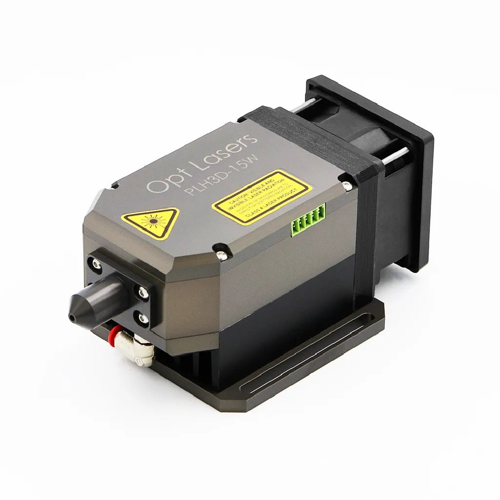
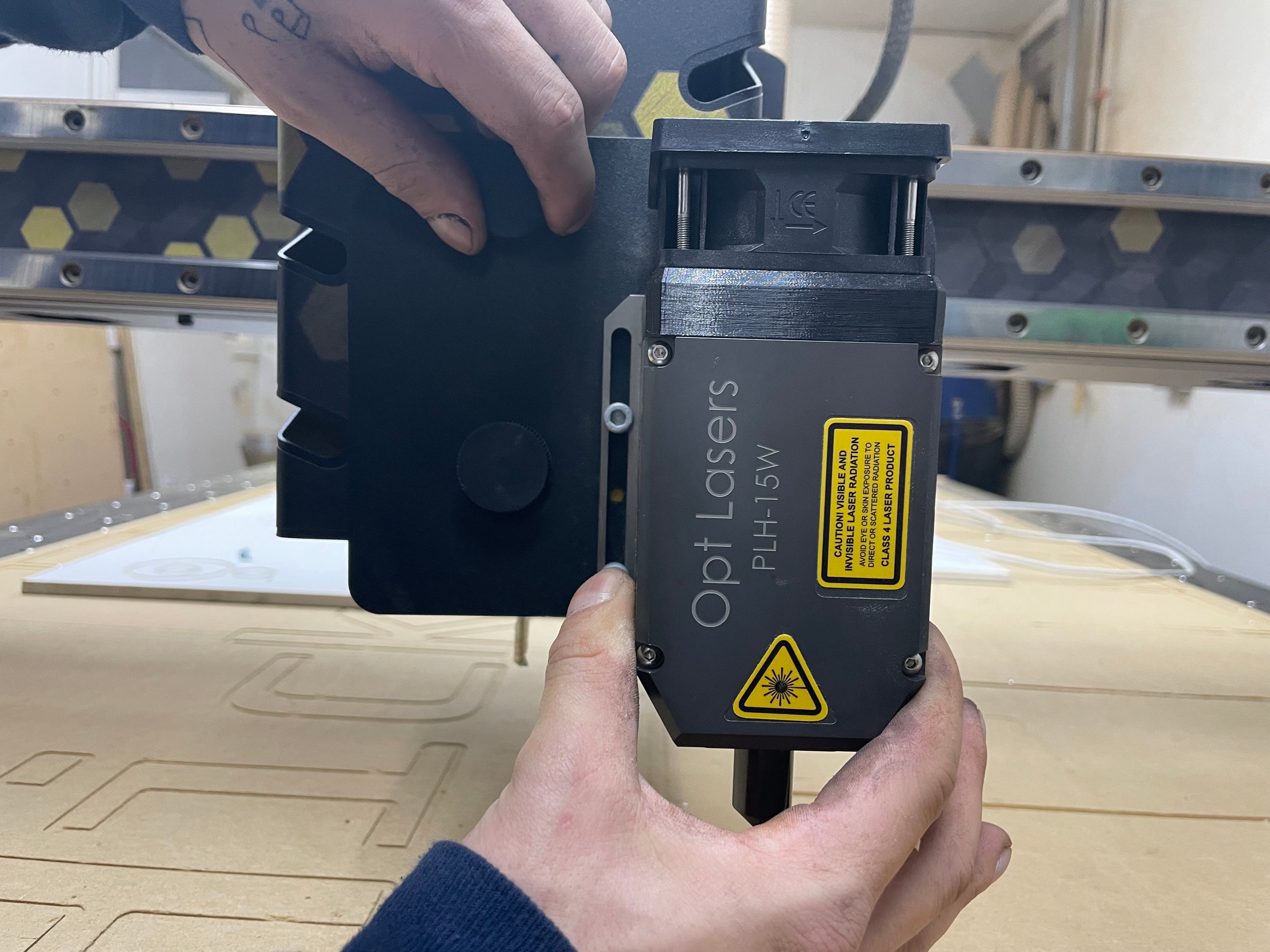
Mount the Laser on the spindle cover with the two thumb screws.
-

Step 2
Plug in the supplied laser communication cable to the control box.
-

Step 3
Connect the supplied laser communication cable to the right side of the laser control box.
-

NOTE
** Make sure the cable is clocked to the top.
-

Step 4
Connect the laser output cable to the left side of the laser control box (the long gray cable). At this time you don't need to worry about running the cable in the drag chain; we will complete the setup first to make sure everything works.
-

Step 5
Connect the power cord to the top of the laser control box and plug the other end into your power outlet (use the American style 110V power adapter that is supplied).
-

Step 6
Connect the laser output cable to the laser.
-

NOTE
** The end of the output cable that connects to the laser is the side with only 4 cables.
-

Step 7
Press the red button to power on the laser.
-

NOTE
** The Armed light should come on and you should hear the laser's internal fan.
If this does not happen you may need to turn the key that's supplied. -

Step 8
Go to the Planet CNC software and click on FILE > IMPORT PROFILE
-

Step 9
Load the laser profile; a download for that profile is available on this page.
-

NOTE
** Go into your settings and double click on your license so it populates the PRIMARY CONTROLLER line, then click OK.
-

Step 10
Click on the spindle button at the top of the screen. This should turn on the laser.
-

NOTE
THE LASER IS A SERIOUS TOOL, PLEASE BE CAREFUL. IT CAN EASILY CAUSE A FIRE IF YOU ARE NOT MINDFUL.


Programing CAM for your OPT Laser
We have set this up to work with Vectric Software (V carve pro / Aspire). You will need the laser extenson module that you can purchase from them
-

Step 1
Open your Vectric software after you have downloaded and installed the laser extension module.
Define your stock size and your work coordinates. -

Step 2
Create or import your design.
-

Step 3
Add a laser tool path to the design.
-

NOTE
** You may need to add the laser as a new tool in your library. The Kerf is .007
For speeds and feeds on the laser, see the graphic below. -

Step 4
Verify that your tool paths are displaying how you want.
-

Step 5
Set your tool path Post Processor to the DIGITAL WOOD CARVER LASER MODULE.
-
Step 6
Save your post processed tool path to a thumb drive and bring it over to your planet cnc laptop. open the file in Planet cnc and set your work coordenates and press play to begin.
-
NOTE
** THE RECOMMENDED FOCAL DISTANCE IS 3MM FROM THE SURFACE OF THE STOCK.
For speeds and feeds on the laser, see graphic below.


Laser Profile Download Link
This is a link to download a .zip file. Do not unzip it.
Note - To switch back and forth from the laser to the router, you will need to load the router profile before using the machine as a router or the laser profile before you use the machine as a laser. We are working on a software update that will control the laser power output via g code (not with S words). This will allow you to use the router or laser without needing to import a different profile every time you switch. It will be one profile for both tools.
Opt Laser Tech Info
-

Base feeds and power settings
-

Laser tech info


Important websites to learn how to use the laser
-

Opt Laser's Website
OPT Laser -

Opt Laser's YouTube page
OPT Laser Youtube -

Vectric Laser Module
Vectric Laser Module -

Opt Laser Facebook Users Group
Opt Laser Facebook Users Group -

ImagR
ImagR -

Opt Laser Facebook File section
Opt Laser File section